How to Integrate IDEA StatiCa with STAAD.Pro – BIM Links in 2026?
What is the purpose to Integrate IDEA StatiCa with STAAD.Pro?
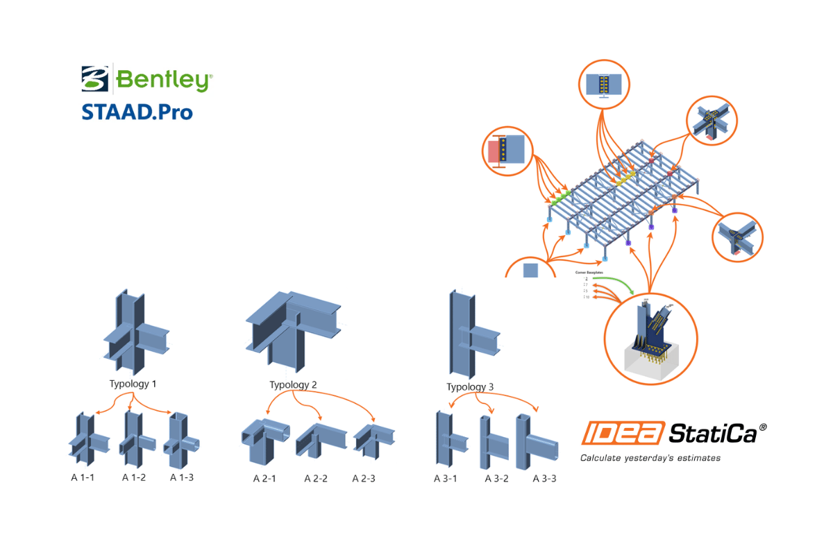
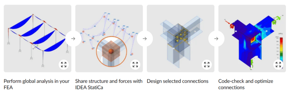
STAAD.Pro is used to build and analyze the global structural model – member sizing, load combinations, and overall stability – while IDEA StatiCa performs detailed, code-based design and checking of individual steel connections and members using the Component-Based Finite Element Method (CBFEM). Neither application is intended to replace the other: STAAD.Pro does not model connection-level plate, bolt, and weld behavior in detail, and IDEA StatiCa is not a global analysis package. The BIM link between the two closes this gap by transferring geometry, member end-forces, cross-sections, and material data for the joints and members of the entire structure or the engineer’s selection, directly from STAAD.Pro model into IDEA StatiCa, without manual re-entry.
This blog explains both ways of setting up the link – the automatic, one-click installation, and the manual (folder-path) method used when the automatic route does not register correctly – followed by what the integration is actually used for once it is active.
Prerequisites: To Integrate IDEA StatiCa with STAAD.Pro
- The latest version of IDEA StatiCa is installed on the workstation.
- A supported version of STAAD.Pro (IDEA StatiCa supports the two most recent major releases of each linked application in any given major IDEA StatiCa release; check the current BIM link compatibility table before installing on an older STAAD.Pro version).
- Microsoft .NET 6.0 or higher is installed, since the BIM link will not function correctly without it.
- Administrator rights on the workstation, since both the BIM link installer and, if needed, the manual User Tools configuration in STAAD.Pro may require elevated permissions.
Methods To Integrate IDEA StatiCa with STAAD.Pro
Method A — Automatic Integration (One-Click BIM Link)
IDEA StatiCa integrates BIM links into supported FEA and CAD software automatically as part of its own installation. In most cases, no separate action is needed in STAAD.Pro at all; where the link needs to be activated or reactivated, use the BIM Link Installer within IDEA StatiCa:
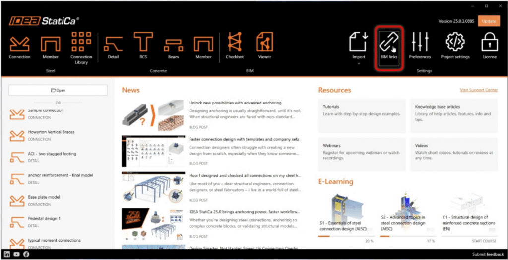
- Step 1: Open IDEA StatiCa and go to the BIM Links tab.
- Step 2: Select Activate your BIM link. This opens the BIM Link Installer, which lists all FEA/CAD applications IDEA StatiCa can integrate with, including STAAD.Pro.
- Step 3: If prompted by Windows with “Do you want to allow this app to make changes to your device? confirm with Yes so the installer can register the plugin.
- Step 4: Locate STAAD.Pro in the list and select Install next to it. The status next to STAAD.Pro should change to Installed once the link is registered successfully.
- Step 5: Open (or restart) STAAD.Pro, open a project, and go to Utilities → User Tools. The entry IDEA StatiCa Checkbot should now be listed in the drop-down menu, confirming the link is active and ready to use.
Engineering Note: A short delay between a new release of STAAD.Pro or IDEA StatiCa and an updated BIM link is normal; if a newly installed major version of either application is not yet listed as supported, check the BIM link compatibility table before assuming the installation has failed.
Method B — Manual Integration (Folder Path / User Tools)
If, after running the automatic installer, IDEA StatiCa Checkbot does not appear under User Tools in STAAD.Pro, the plugin can be added to STAAD.Pro BIM link-for steel connection design manually by pointing to STAAD.Pro directly to the plugin executable’s installation folder:
- Step 1: In STAAD.Pro, go to the Utilities tab and select User Tools → Configure.
- Step 2: In the Configure Tools dialog, add a new user-defined tool using the Add (or equivalent ‘+’) option.
- Step 3: In the Command field, enter the full path to the plugin executable, matching the IDEA StatiCa version installed on the workstation, for example: C:\Program Files\IDEA StatiCa\StatiCa 26.0\IdeaStaadProPlugin.exe
- Step 4: In the Initial Directory field, enter the folder containing that executable, for example: C:\Program Files\IDEA StatiCa\StatiCa 26.0\
- Step 5: Optionally rename the tool entry to something recognizable, such as IDEA StatiCa Checkbot, so it is easy to identify in the User Tools menu.
- Step 6: Confirm with OK to save the new tool entry.
- Step 7: Restart STAAD.Pro if the new entry does not appear immediately in the User Tools drop-down list.
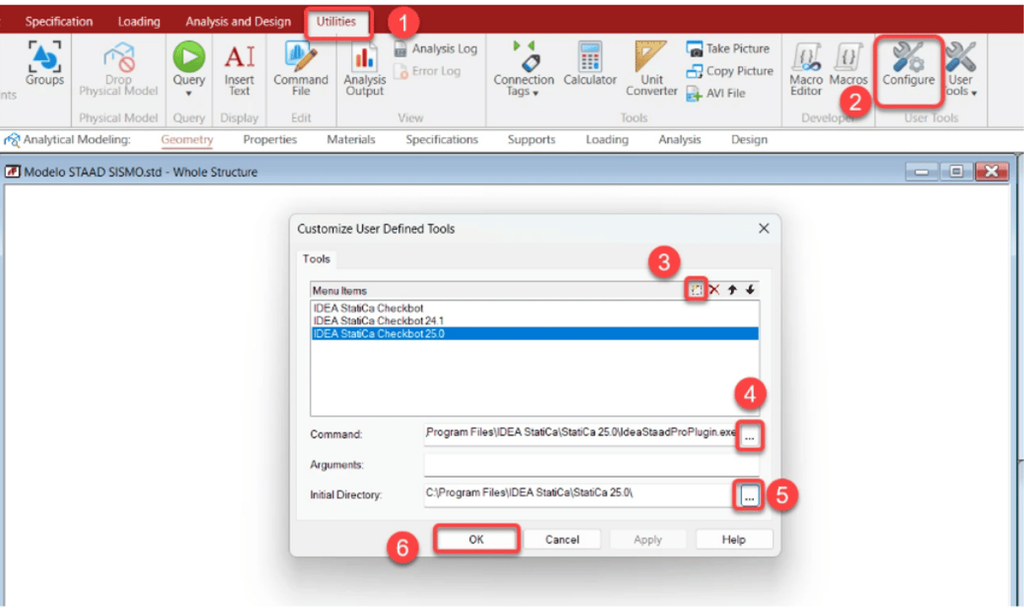
Engineering Note: The version number in the folder path (e.g., “StatiCa 26.0”) must match the IDEA StatiCa version actually installed on the machine – if a different or older version is installed, browse to the corresponding IDEA StatiCa installation folder under C:\Program Files\IDEA StatiCa\ and select the matching plugin executable rather than assuming the path above is universal.
How to verify the integration of IDEA StatiCa with STAAD.Pro?
- Open STAAD.Pro project (a simple test model is sufficient) and run the analysis, since the BIM link transfers analysis results (member end-forces) along with geometry, and an unanalyzed model will not provide forces to export.
- Go to Utilities → User Tools and confirm IDEA StatiCa Checkbot is listed.
- Launch IDEA StatiCa Checkbot from within STAAD.Pro and confirm that it opens without error and recognizes the active STAAD.Pro project.
- Select a joint or multiple joints in STAAD.Pro model and attempt an export to confirm that geometry, cross-sections, and end-forces appear correctly in Checkbot before relying on the link for a live project.
Moving Structure from STAAD. Pro to IDEA StatiCa Checkbot
- In STAAD.Pro, run the analysis so that member end-forces are available for the load cases of interest.
- Launch IDEA StatiCa Checkbot from the User Tools menu (or directly from IDEA StatiCa, depending on workflow preference).
- Select the joints and/or members to be checked – any number can be selected together for batch export.
- Export the selection into Checkbot, where geometry, cross-sections, materials, and end forces for the selected load cases are transferred automatically.
- Open the imported joint(s) in IDEA StatiCa Connection (or Member, as applicable), and add the connection details – plates, bolts, welds – that do not exist in the global STAAD.Pro model, and run the code check.
- Review the Unbalanced Forces table for each imported load case before finalizing the check (see Document 5 of this series), since BIM-imported loads can occasionally be incomplete depending on how the load was defined in STAAD.Pro.
- If the STAAD.Pro model is subsequently revised, Checkbot is reopened, and the synchronization function is used to update the affected connections rather than re-exporting from scratch.
Before & After Limitations: Integration of IDEA StatiCa with STAAD.Pro
- Supported STAAD.Pro versions change over time with new releases; always confirm the current supported/obsolete version table before assuming an older STAAD version.Pro installation is compatible.
- The BIM link transfers what STAAD.Pro’s analytical model actually contains member geometry, cross-sections, materials, and end forces. Note that plates and surfaces and their relevant forces are not supported.
- Load combinations within Load Combinations are not supported.
Practical Recommendations
- Attempt the automatic (one-click) installation first via IDEA StatiCa’s BIM tab; only fall back to the manual folder-path method in Section 5 if Checkbot does not appear under STAAD.Pro’s User Tools after installation and a restart.
- Always analyse the STAAD.Pro model before attempting an export, since unanalyzed models have no end-forces to transfer.
- Keep IDEA StatiCa and STAAD.Pro on supported, compatible versions, and check the BIM link compatibility table after any major upgrade of either application.
- Treat the exported connection as a starting point, not a finished model – add and verify connection details, and check the Unbalanced Forces table before relying on the code-check result.
What You Get by Integrating
- Elimination of manual data re-entry: Member geometry, cross-sections, materials, and end forces are transferred directly from STAAD.Pro to IDEA StatiCa removes manual errors in load paths.
- Synchronization with the source model: if the STAAD.Pro model changes – a section size, a load case, a support condition – the corresponding forces and members in IDEA StatiCa can be re-synchronized with the latest analysis.
- Batch selection and export: Any number of joints, members or a complete Structural Steel Connection Design (upto 500 Nodes) can be selected in STAAD.Pro and exported together, allowing a multiple-connection design to be brought into IDEA StatiCa.
- Centralized management via Checkbot: The BIM link is managed through IDEA StatiCa Checkbot, which tracks which joints have been imported, their synchronization status, and lets the engineer manage large projects with many connections without losing track of what has and has not been checked.
- A consistent, auditable data path: Since the connection design in IDEA StatiCa steel is traceable back to a specific STAAD.Pro load case and member, the workflow is easier to justify to reviewers, checkers, and third-party approval authorities than a manually re-built connection model.
Still Have Questions?
If you are still unsure about the IDEA StatiCa–STAAD.Pro BIM link, have encountered an issue during setup, or are not sure how to proceed, our technical team can help. Call us: +91 73311 11138. Or contact us through the Nhance Digital website.
Frequently Asked Questions
1. How does the IDEA StatiCa BIM Link work?
Ans. The BIM Link connects the global structural model with detailed connection design, transferring supported geometry, member forces, sections, and materials.
This saves engineers from manually rebuilding model information and provides a faster starting point for connection checks. Nhance Digital Solutions can help you set up the BIM workflow and get started.
2. What information can be imported into IDEA StatiCa?
Ans. The integration can transfer supported member geometry, cross-sections, materials, and analysis forces from the structural model.
Engineers can then add connection-specific details such as plates, bolts, and welds in IDEA StatiCa.
If you’re unsure what your model can transfer, Nhance Digital Solutions can guide you through the workflow.
3. Can I design steel connections directly from my analysis model?
Ans. Yes. Selected joints or members can be transferred to IDEA StatiCa for detailed steel connection design and code checking.
This creates a connected workflow from global analysis to connection verification without recreating the entire model. Nhance Digital Solutions can assist with implementing this workflow for your projects.
4. What should I check before using the BIM Link?
Ans. Make sure your software versions are compatible, the BIM Link is installed correctly, and the structural model has been analyzed before exporting.
It is also important to verify the transferred forces and review the connection results before finalizing the design. Need help checking your setup? Nhance Digital Solutions can provide technical guidance.
5. How can BIM integration improve steel connection design?
Ans. IM integration reduces repetitive data entry, helps maintain consistency with the analysis model, and makes it easier to manage multiple connection designs.
It can also simplify updates when the source model changes, improving the overall engineering workflow. Nhance Digital Solutions can help you explore and implement an efficient IDEA StatiCa workflow.